RotorDrive
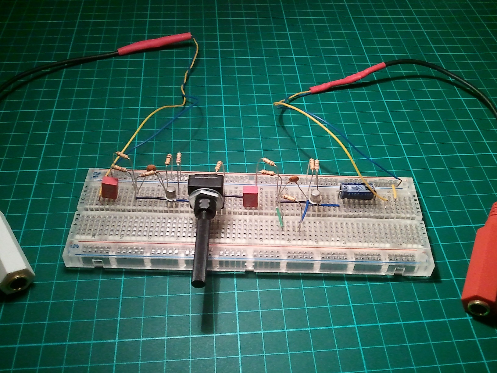
 RotorDrive is my first attempt at building a solid state DIY Guitar Overdrive. Design is based on a dual transistor gain stage for power overdriving.
Design constraints were kept to the minimum : only components with nominal values (multiples of 10), only one gain control for the first stage.
The distortion is asymetrical and provided by either transistor power saturation or the unique diode at transistor stage 2.
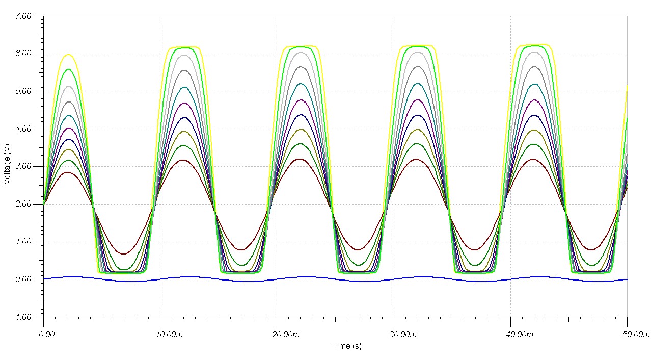
When “DRIVE” switch is open, Rotordrive is in BOOST mode, providing a slight crunchy overdrive on single coil microphones, reasonalby maintaining the instrument timbre at the output.
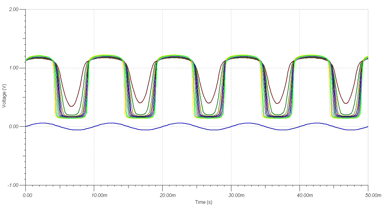
When “DRIVE” switch is closed, unit is in Overdrive mode, with highly distorted sound and weird harmonics.
The sound of this medal is somehow quite “brute force”. I recommend to combine it with a tone shaping network like the basic tone filter proposed here.
The volume output pot is optional, recommended mainly for assembly in a case on a final product.
Schematic
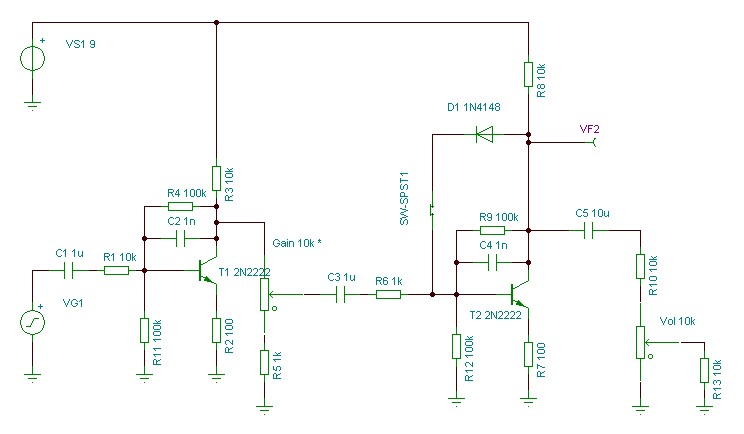
The “DRIVE” switch is SPT1. The “Gain” potentiometer is for … Gain !
The Gain can be modified by changing the feedback resistors R4 and R9
Changing the transistors itself should result in higher gain (ex switching to BC550).
Generally, this schematic can be easily extended on use. Consider having a good power supply regulation, according to the gain of this dual stage.
Note : R13 should not be installed, it has been added for simulation purpose. The output of this pedal is the tip of the volume potentiometer.
Operation
A few time diagrams from Tina are shown herebelow to illustrate both boost and overdrive modes.
Both diagrams represent the effect of the Gain potentiometer from 0 to 100% when Rotordrive is fed by a 60mV peak input signal, close to a standard Mic.


