Table of Contents
Tone Filter
Here is a schematic and some playing around on a simple way to performe tone shaping in audio designs. Theoritical discussion is discussed, ending with an application example from the legendary guitar pedal Big Muff from Electro Harmonics.
Concept
This simple tone filter is a mono-potentiometer tone control built in a discrete simple bridge.
- When at middle position, the frequency response is either flat or band-active.
- On the extremes, it operates in low and high pass filter
This simple tone control is easy to set up and can provide quick tone shaping capability to a simple DIY analog synth or gutar pedal.
Schematic of the Flat response version
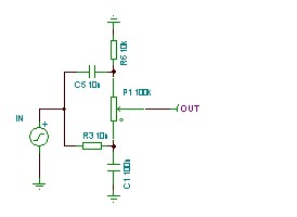 Two first order filters, one lowpass and one highpass, are fed with the input signal. The output is the tip of a potentiometer that provides a mix of the two filters outputs.
Characteristics
- operating frequency is given by f = 1 / (2 x Pi x R x C) Hz
- potentiometer is Linear type
- Both filters R & C have to be equal
Impedances
- Potentiometer total resistor shall at least be one order of magnitude greater than R
- Input source impedance shall be at least one order of magnitude lower than R
- Output load impedance shall be at least one order of magnitude greater than potentiometer
In the example here, frequency is f = 1/ (2 x Pi x R x C) = 1/ (6,283 x 10 000 x 0.00000001) = 1600 Hz, as a consequence Pot value is 10k x 10 = 100k.
Frequency response
Here is the frequency response of the tone filter example above :
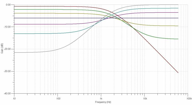
- Grey curve is the Pot at 100% - highpass filter - with -0.4dB Gain
- Blue curve is the Pot at 50% - allpass filter - with -6dB Gain
- Red curve is the Pot at 0% - lowpass filter - with -0.4dB Gain
Time response
Here is the time response of the tone filter example above when fed with a 1Hz square wave :
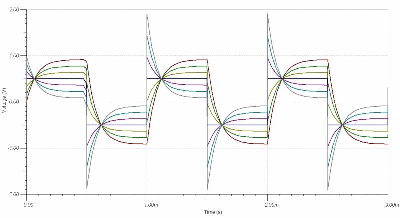 The color scheme is equivalent to the one described in the Frequency response chapter.
Playing with parameters
R and C unmatching
Unmatching the two filters resluts in creating specific frequency responses. This means that you are mixing signals at the output of two different frequency filters, resulting in the following behaviour:
Highpass filter freq < Lowpass filter freq
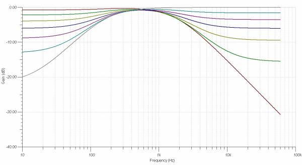 The result is a resonance peak.
Position of the peak depends on the Potentiometer position, and drifts between the two frequencies of the two lowpass and highpass networks.
Highpass filter freq > Lowpass filter freq
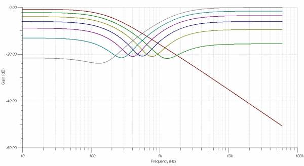 The result is a notched frequency.
Position of the notch depends on the Potentiometer position, and drifts between the two frequencies of the two lowpass and highpass networks.
Example : Big Muff tone control
The legendary EH Big Muff pedal uses such network for tone control.
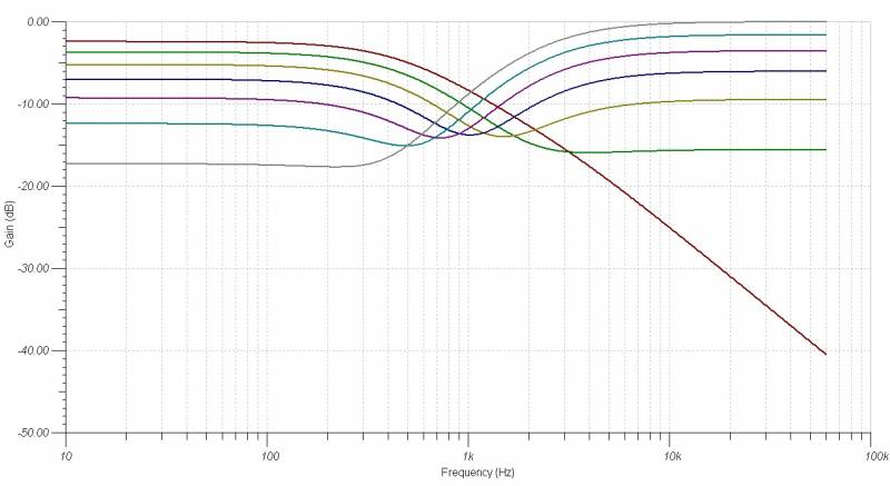
The designers choice is an asymetrical notched network as shown here.
Impedances are also unbalanced which results in an unbalancing of the 50% pot notch gain center position drift : the shape of the filter response is given herebelow.
Conclusion
This handy schematic provides easy tone shaping to an electronic design.
It main drawback is to have a -6dB gain when symetrical and center taped, whereas its strong advantage is to be 5 component big.
Hard to beat !


